
Stretch film manufacturing is a continuous conversion process: a defined resin system is metered, melted, filtered, formed as cast or blown film, cooled, wound, slit, tested, and released as finished rolls. Each stage changes what the buyer ultimately experiences—gauge consistency, cling, puncture behavior, stretch response, unwind force, roll geometry, and load stability. A useful specification therefore starts with the wrapping application and test method, not with a resin name or a single headline property.
Understand the Two Manufacturing Routes
For polymer background, consult the NIH PubChem polyethylene overview before comparing finished-film claims.
For polymer background, consult the NIH PubChem polyethylene overview before comparing finished-film claims.
Polyolefin film is commonly produced by cast-film or blown-film extrusion. Both routes melt a thermoplastic in an extruder and force it through a die, but they form and cool the web differently. The LyondellBasell polyolefin film extrusion guide describes both methods and shows why process conditions, die design, cooling, and drawdown must be considered together rather than treated as interchangeable settings.
Cast stretch film extrusion
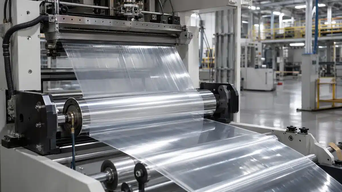
On a cast line, one or more extruders feed a flat die. The melt exits as a wide curtain, contacts a temperature-controlled chill roll, solidifies rapidly, and continues through web-handling and winding stations. Fast quenching can support clear appearance and tight gauge control, but the result still depends on the exact resin, layer arrangement, die profile, air gap, cooling contact, line speed, and winding conditions.
Blown stretch film extrusion
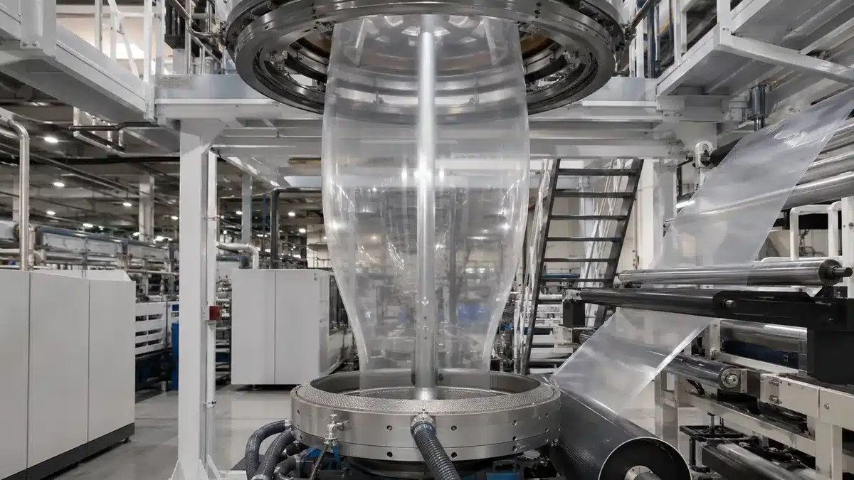
On a blown line, melt exits an annular die as a tube. Internal air inflates the tube into a bubble, an air ring cools it, and a collapsing frame converts it into a flat web before nip and winding. Bubble geometry and cooling create orientation in both machine and transverse directions. That does not make every blown film stronger in every test; thickness, formulation, specimen direction, method, and conditioning still control any valid comparison.
Important: Cast and blown are manufacturing routes, not complete performance grades. A sourcing decision must compare actual film specifications and test reports under matching methods and conditions.
Step 1: Define the Finished-Roll Specification
Production control begins with a specification that describes the use case. “LLDPE stretch film” is not enough because the same polymer family can be processed into different structures, gauges, cling configurations, and roll formats. The manufacturing team needs measurable targets and a release plan before selecting a recipe or line setup.
- Application: hand wrapping, machine wrapping, power pre-stretch, bundling, or another defined use.
- Load and equipment: pallet geometry, edge hazards, weight distribution, wrapping pattern, carriage type, and available pre-stretch setting.
- Film construction: cast or blown route, mono-layer or coextruded design, cling side, color, surface treatment, and any product-specific additive functions.
- Dimensions: nominal thickness, allowed tolerance and measurement method, width, roll length or net mass, core inside diameter, and maximum roll diameter.
- Performance: tensile response, puncture or impact behavior, cling, coefficient of friction, unwind force, elastic recovery, and applied-load containment where relevant.
- Traceability: lot definition, sampling plan, conditioning, acceptance criteria, records, and change-control expectations.
A buyer should state which values are nominal, which are guaranteed limits, and which are for information only. Test direction matters: machine-direction data should not be substituted for transverse-direction data. Likewise, a laboratory film result is not automatically an applied pallet result.
Step 2: Select and Meter the Resin System
Linear low-density polyethylene is widely used in stretch-wrap formulations, while other polyethylene grades or compatible modifiers may be selected for processing or targeted functions. LyondellBasell’s stretch-wrap application page notes that customers use LLDPE, LDPE, and HDPE grades in blends or coextruded layers for different roles. That general guidance does not define a BestY Pack formula or prove the performance of a finished film.
The approved bill of materials may include a base resin, a cling system, processing aid, antiblock or slip components, color concentrate, UV stabilizer, or other additives. Each ingredient must be compatible with the chosen structure and target use. Food-contact, recycled-content, or sustainability claims require product- and market-specific documentation; a polymer name or supplier brochure alone is not sufficient.
- Verify resin and additive identity against the approved bill of materials and current supplier documents.
- Protect pellets and concentrates from contamination, mix-up, and unapproved regrind or purge material.
- Meter each component with calibrated equipment appropriate to the required dosing accuracy.
- Record lot numbers, actual feed settings, line assignment, and any approved deviation.
Drying or special handling should follow the exact material supplier’s instructions; it should not be assumed merely because the material is called polyethylene. In a coextruded film, every extruder has its own feed stream, so a dosing error may alter layer ratio even when total film thickness appears acceptable.
Step 3: Melt, Mix, and Filter the Polymer
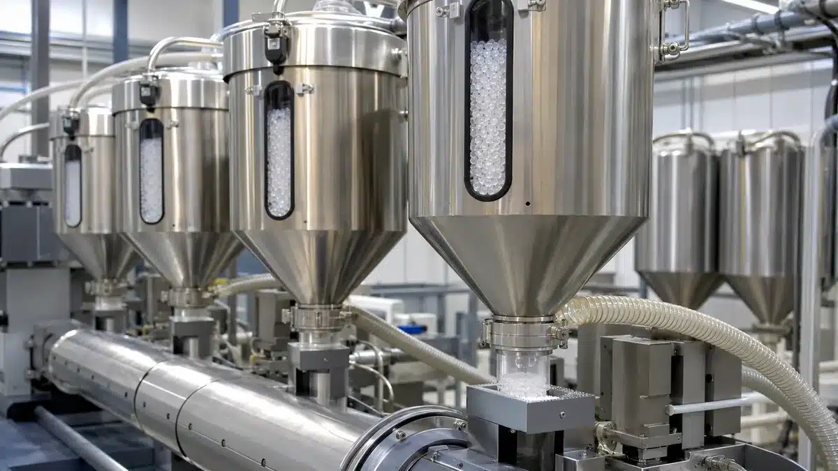
Inside the extruder, a rotating screw conveys pellets through heated barrel zones. Heat from the barrel and shear from the screw produce a pressurized, homogeneous melt. The correct temperature profile is grade-, screw-, output-, and equipment-specific; publishing one universal melting temperature would be misleading.
- Establish stable feeding before raising output so the screw does not alternate between starved and flooded conditions.
- Control barrel, adapter, feedblock, and die temperatures within the approved process window.
- Monitor melt pressure, motor load, and melt temperature for trends rather than relying on heater setpoints alone.
- Pass the melt through the approved screen pack or filtration system and change it using a documented criterion.
- For coextrusion, balance extruder outputs and combine the streams in the approved layer order and ratio.
Unmelted particles, degraded polymer, contamination, unstable pressure, or poor layer distribution can appear later as gels, die lines, weak regions, optical defects, or inconsistent cling. A filter may remove some contamination, but it cannot correct an incompatible formulation or excessive residence time.
Step 4: Form and Cool the Film
The die converts pressurized melt into a continuous film, and cooling fixes much of the resulting morphology and web stability. This is the point where the cast and blown routes diverge most visibly.
On a cast line
The flat die distributes melt across the width. Automatic or manual die adjustment, melt uniformity, deckling, air gap, vacuum or air-knife assistance, chill-roll temperature, and roll contact can all influence gauge and surface appearance. The edges are normally trimmed because neck-in and edge instability can make them unsuitable for the saleable web. Edge trim may be recycled only under an approved, traceable formulation rule.
On a blown line
The annular die forms a melt tube, which is inflated and drawn upward. Blow-up ratio, take-off speed, frost-line position, cooling-air balance, bubble stability, collapsing geometry, and nip alignment interact with thickness and MD/TD orientation. Operators should control the approved process window and use measured film results; a stable-looking bubble alone does not prove a conforming film.
Neither route requires a separate stretching stage for every conventional stretch film. Stretch behavior can come from the resin system and the orientation developed during forming and drawdown. A manufacturing pre-stretch or additional orientation step is product-specific and should be documented separately rather than assumed.
Step 5: Stabilize Gauge, Cling, and Web Tension
After solidification, the line must keep the web flat and centered while controlling thickness profile, surface interaction, and tension. These controls are connected: a gauge band can create a hard lane in the roll, excessive tension can stretch thin areas, and an unsuitable cling or slip balance can cause blocking or unstable transport.
- Trend thickness across the web and along the roll using the approved contact or non-contact method.
- Confirm which side is intended to cling and protect that surface from contamination or unintended treatment.
- Coordinate nip pressure, draw ratio, guide alignment, and tension zones so the web tracks without wrinkles.
- Allow for additive migration or conditioning time when the approved formulation makes cling or COF time-dependent.
- Separate appearance checks from performance checks; a clear roll can still fail gauge, recovery, puncture, or load tests.
Thickness results need the instrument, sampling locations, unit, and statistical treatment. COF results need the film side, mating surface, conditioning, speed, and test conditions. Cling results likewise require a defined method and stretched or unstretched state. Without those details, numbers from different suppliers are not safely comparable.
Step 6: Wind the Master Roll
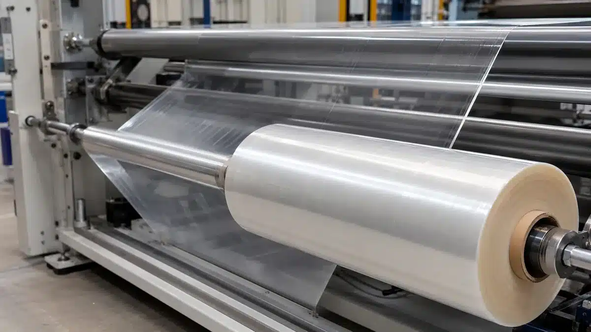
Winding turns a continuous web into a stable master roll that can be stored and converted. The winder coordinates web tension, nip or lay-on pressure, torque, speed, roll diameter, core condition, and changeover. The preferred taper and pressure profile depends on film gauge, cling, modulus, roll width, and downstream unwinding.
- Inspect the core and align it to the web before the transfer.
- Establish a secure start without folds, trapped debris, or excessive local pressure.
- Adjust tension and nip as diameter increases according to the approved winding recipe.
- Monitor edge alignment, wrinkles, entrained air, hard bands, telescoping, and roll temperature.
- Close the roll, identify the lot, and protect it from deformation or contamination before conversion.
A master roll can pass film-property tests yet still convert poorly if it is wound too hard, too soft, or unevenly. Winding quality is therefore part of product performance, not merely a storage convenience.
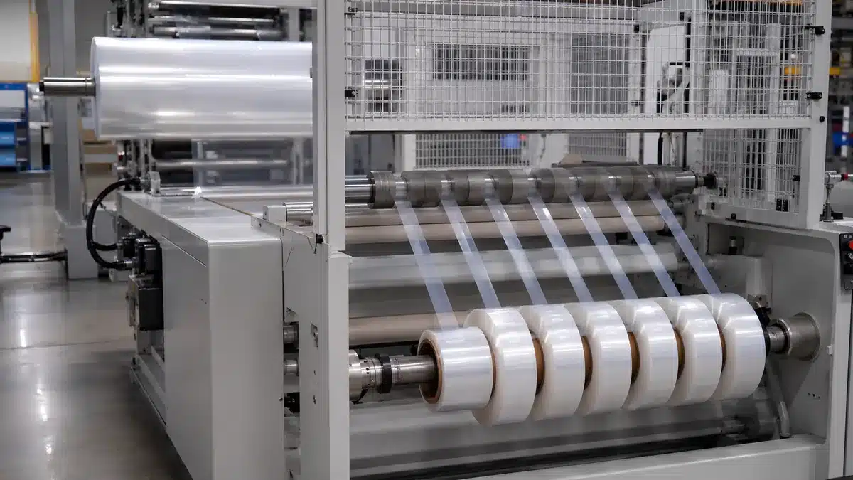
Step 7: Slit and Rewind Finished Rolls
Slitting and rewinding convert the.
- Verify the master-roll identity and release status before loading it.
- Set the slitting method, blade condition, web path, and finished widths.
- Control unwind brake, intermediate tension, rewind torque, and lay-on pressure.
- Check edge quality, width, roll build, core alignment, telescoping, and blocking during the run.
- Confirm roll length or net mass with the declared method, then label and pack the roll for traceability and transport.
A clean cut edge matters because edge damage can initiate tears during high-speed machine wrapping. Roll geometry also affects carriage loading and unwind behavior. Acceptance should therefore include dimensional and functional checks, not only the appearance of the outer wrap.
Step 8: Test and Release the Production Lot
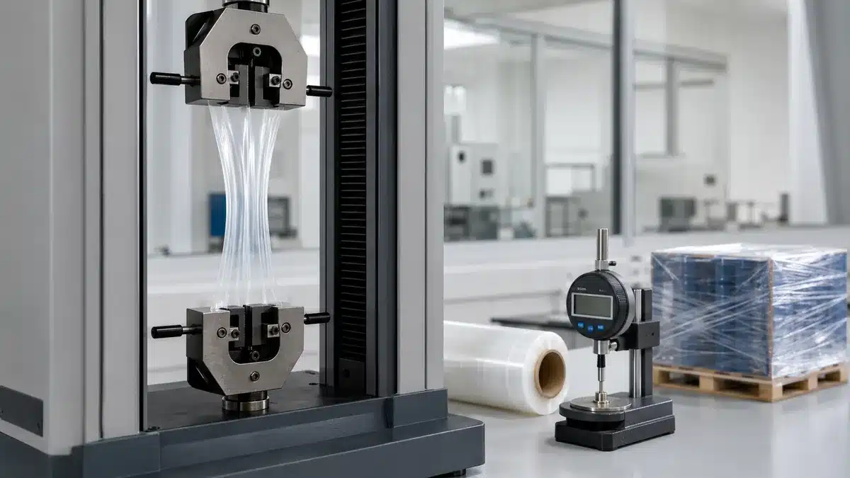
Release testing should connect the film specification to the wrapping application. The current ASTM catalog includes methods for thin-film tensile properties, impact, friction, cling, recovery, and applied stretch-film performance. The method edition, specimen conditioning, thickness, film direction, speed, apparatus, unit, and sampling plan must travel with any reported result.
Film-level verification
- Thickness: use the agreed sampling pattern and instrument; report nominal, individual readings, and variation as specified.
- Tensile properties: ASTM D882-26 covers tensile properties of thin plastic sheeting; report MD and TD separately where required.
- Impact or puncture: ASTM D1709-24 addresses free-falling dart impact, while stretch-wrap puncture may use another agreed method; do not normalize unlike methods or thicknesses.
- Friction and cling: ASTM D1894-24 addresses static and kinetic COF, and ASTM D5458-95(2025) addresses peel cling of stretch wrap in stretched and unstretched conditions.
- Recovery and retention: ASTM D5459-95(2025) addresses machine-direction elastic recovery, permanent deformation, and stress retention.
Applied-load verification
Film data cannot by itself prove pallet stability. Applied trials should define the load, wrapper, pre-stretch setting, film weight, wrap pattern, containment-force measurement, handling sequence, and acceptance limit. ASTM lists D8314-20(2025) for performance testing of applied stretch films and other methods for vibration and impact evaluation of unitized loads. Use the edition and procedure agreed for the project.
The laboratory and production records should identify the sampled lot and confirm that the test method is appropriate for the claim. A management-system certificate does not replace film testing, and a passing film test does not replace a validated load when distribution risk is the decision.
Common Defects and Their Investigation Path
A visible symptom rarely has only one cause. Investigation should start with the affected roll and lot, then move backward through conversion, winding, web handling, cooling, die, filtration, extrusion, and material records. The table lists control directions to investigate, not automatic diagnoses.
| Symptom | Process areas to investigate | Verification |
|---|---|---|
| Gauge bands or uneven roll hardness | Die profile, melt uniformity, cooling, thickness control, tension and nip | Cross-web gauge map, roll-hardness profile, process trends |
| Gels, specks or die lines | Material identity, contamination, residence time, filtration, die condition | Defect sample, screen-change record, purge and material-lot history |
| Wrinkles or telescoping | Web alignment, tension zones, nip, core condition, roll storage | Roll geometry, tension recipe, edge alignment and storage record |
| Low or uneven cling | Cling-side orientation, dosing, surface contamination, conditioning time | Defined cling method, film side, lot age and conditioning |
| Blocking or difficult unwind | Additive balance, winding pressure, storage temperature, film surface | Unwind-force trend, roll hardness, storage history and COF or cling test |
| Premature tears in use | Edge quality, thin spots, gels, puncture exposure, wrapper settings | Edge inspection, gauge map, tensile or puncture data and applied trial |
Corrective action should be verified on new material, not inferred from a changed machine setting alone. When more than one variable changes, the record should preserve enough information to determine which change actually affected the result.
What Buyers Should Verify Before Approval
A manufacturing overview is most useful when it improves supplier qualification. Ask for evidence that connects the offered roll to the proposed equipment and load, while avoiding requests for unsupported universal claims.
- Which cast or blown route, layer structure, resin grades, and additive functions apply to the quoted item?
- Which dimensions are controlled, by what method, and with what tolerance and sampling plan?
- Which side clings, how are COF and cling measured, and how does conditioning time affect release testing?
- Which tensile, puncture or impact, recovery, unwind, and roll-build checks are included in the certificate or lot record?
- What wrapper, pre-stretch, load, wrap pattern, and distribution sequence will be used for application validation?
- Which changes to resin, additive, layer ratio, line, die, core, or test method require notification or requalification?
- If food contact, recycled content, or another regulated claim matters, which exact product, structure, market, use, time, and temperature are covered by the documents?
The safest approval path is a controlled sample or trial using the intended wrapper and representative load, followed by a written specification that captures the test conditions and change-control rules. That approach converts process knowledge into evidence for the actual purchasing decision.
Conclusion: Manufacturing Control Must Match the Use Case
Stretch film is made through a linked sequence of specification material control extrusion film forming cooling web handling winding converting and verification Cast and.
Related Bestypack Resources
- Machine Stretch Film Blown & Cast
- Cast Stretch Film
- PE Stretch Film Polyethylene Packaging Film
- stretch film
- Types of PE Film: Features and Applications
- Manufacturing Process of Flexible Packaging Film
 English
 Japanese
 French
 Spanish
 Korean
 Italian
 Portuguese
 Dutch
Dutch Arabic
 Russian
 German