
Choosing shrink film is not simply a choice of polymer or gauge. A workable specification must connect eight elements: construction, dimensions, free shrink, shrink force, the seal-and-tunnel window, mechanical performance, optical performance, and end-use protection. Each element affects the others, so an isolated “typical” value rarely predicts a finished package. Buyers should request method- and condition-specific data, then confirm the candidate film on the actual product and packaging line before commercial approval.
1. Material and Layer Construction
For environmental claims, compare the design with the U.S. EPA’s recycling guidance and the actual local collection system.
For environmental claims, compare the design with the U.S. EPA’s recycling guidance and the actual local collection system.
Start by identifying what the film actually is. “Polyolefin,” “polyethylene,” or “PVC” names a broad polymer family, not a complete construction. Films within one family can use different resin grades, orientation routes, layer sequences, surface treatments, slip or anti-fog additives, crosslinking processes, and seal layers. Those choices can change sealing behavior, optics, toughness, shrink response, and regulatory documentation.
The useful comparison is therefore not a simple ranking of polymer names. It is a comparison of equally described constructions:
| Identification level | What it tells the buyer | What remains unknown | Evidence to request |
|---|---|---|---|
| Polymer-family label | A broad chemistry category | Grade, layer sequence, orientation, additives, and finished-film performance | Full material and construction description |
| Grade or formulation identifier | Which commercial formulation is being offered | Whether the supplied roll matches the tested construction and thickness | Current TDS and product-specific specification |
| Layer and surface description | The function of seal, core, skin, treatment, coating, or printed surfaces | Actual test results and suitability for the buyer’s process | Layer order, total thickness, surface treatment, and applicable reports |
| Intended-use declaration | The application and market considered by the supplier | Performance on the buyer’s product, machine, and distribution route | Use limitations, target-market documentation, and approved sample |
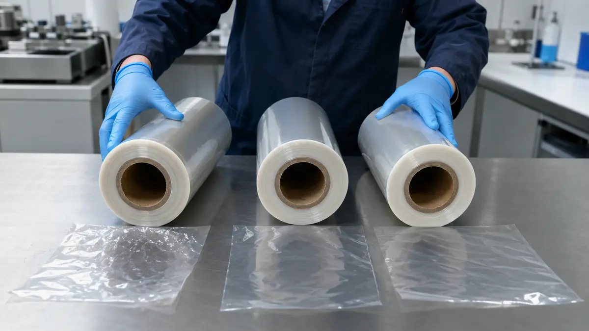
This construction record is the parent of every later comparison. A test report for a different grade, thickness, layer order, surface, or additive package should not be treated as evidence for the offered film. Material identity alone also cannot prove food-contact status, recyclability, barrier, seal strength, or package performance.
2. Gauge, Dimensions, and Roll Format
Thickness affects material usage and can influence strength, heat transfer, sealing, and roll length, but it should not be selected by the slogan “thicker is better.” The right gauge is the lightest construction that meets the agreed package and process requirements with an acceptable operating margin. Compare candidates only when the measurement basis and film construction are clear.
A purchase specification should state:
- Nominal thickness in micrometres or mils, the permitted tolerance, the sampling plan, and the measurement method. ISO 4593 describes mechanical scanning for non-embossed film; another agreed method may be needed for a different surface.
- Web width or centre-fold width, dimensional tolerance, fold alignment, and any allowable edge variation.
- Roll length or net mass, core inside diameter and material, winding direction, maximum outside diameter, splice allowance, and roll identification.
- Flatness, blocking, telescoping, edge condition, and unwind requirements that matter to the machine.
- Storage temperature range, protection from direct heat and sunlight, inventory rotation, and the conditioning time required before use.
Important: Gauge terminology can be misunderstood across markets. Put the SI thickness, conversion basis, tolerance, and measurement method on the same specification instead of relying on a “gauge” label alone.
Dimensions must also fit the equipment. A roll that meets film-property targets can still be unusable if the core, outside diameter, web width, winding, or splice policy conflicts with the unwinder and controls. Confirm these fields before a trial roll is produced.
3. Free Shrink and MD/TD Balance
Free shrink describes the irreversible dimensional reduction of an unrestrained specimen after a defined heat exposure. For one direction, the basic calculation is:
Free shrink (%) = ((L0 − L1) / L0) × 100
where L0 is the initial gauge length and L1 is the length after the stated heating and cooling procedure. The result must identify the test method, specimen conditioning, temperature, exposure time, and direction. ASTM D2732 covers unrestrained linear thermal shrinkage at given specimen temperatures for film and sheeting within its stated scope.
Machine direction (MD) and transverse direction (TD) results belong side by side. A balanced film may show a similar response in both directions, while a preferentially oriented construction is designed to respond differently. Neither pattern is universally better. Package geometry, seal position, excess film, and the risk of distortion determine the useful balance.
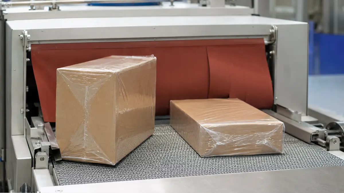
A single result such as “60% shrink” hides the temperature response. Request a shrink curve with MD and TD values at agreed temperatures and time, using the same specimen preparation for each point. Then compare that curve with the tunnel’s practical heat-transfer range and the product’s heat tolerance. Free-shrink data can screen candidates, but it does not include restraint from the product, seals, trapped air, conveyor contact, or nonuniform tunnel airflow. Finished appearance still requires a package trial.
4. Shrink Force and Product Sensitivity
Shrink force is not shrink percentage. It describes the force or stress developed as an oriented film attempts to contract while wholly or partly restrained. ASTM D2838 includes procedures for shrink tension and orientation release stress; its procedures differ in how the specimen is restrained or allowed to shrink before restraint. The procedure, temperature, direction, specimen dimensions, and reporting unit must accompany the value.
The decision follows a risk chain:
- Trigger: Heat releases orientation while the film is constrained by a product or bundle.
- Cause: The film develops force as a function of construction, direction, temperature, and the degree of permitted movement.
- Possible consequence: A light carton, paper stack, tray, label, or delicate multipack can bow, crush, curl, or shift. Too little containment may also leave a bundle unstable.
- Control direction: Define the product’s sensitivity, compare force data under the same procedure and temperature, and observe dimensions and damage during a line trial.
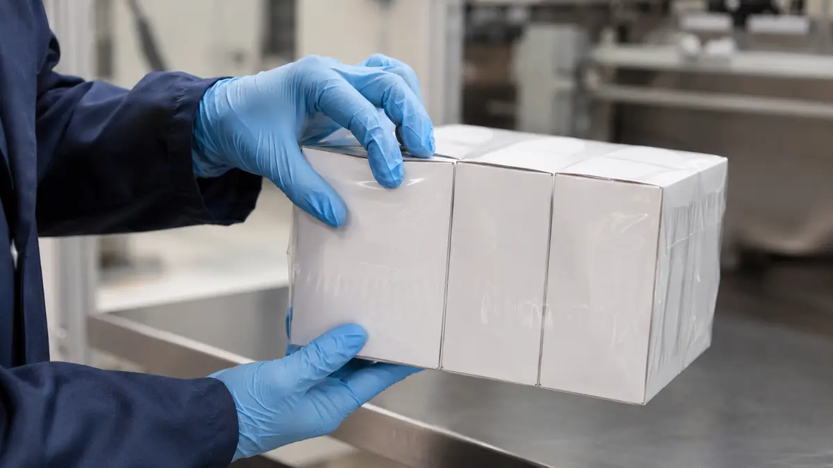
Warning: There is no universal “good” shrink-force number. A value suitable for rigid metal components may be unacceptable for a thin paperboard carton, and results from different D2838 procedures or temperatures are not directly interchangeable.
Record both package appearance and product dimensional change after shrinking and after an agreed conditioning period. That makes the acceptance decision about the packaged system, not the film value in isolation.
5. Seal and Tunnel Operating Window
A robust film should run through a range of conditions not at one fragile set point The working window includes the seal-forming step film transport heat exposure airflow cooling and the.
- Document the line and product. Record sealer type, sealing element, jaw or wire condition, pressure where controlled, dwell or cycle speed, tunnel zones, airflow arrangement, belt speed, perforation, package geometry, and product heat limit.
- Define seal test conditions. Make seals across a planned range while holding the other variables constant. Record the sealed surfaces, temperature or energy setting, pressure, dwell, cooling time, specimen width, peel technique, and failure mode.
- Screen seal strength and continuity. ASTM F88/F88M measures the force required to separate a test strip containing a seal and identifies failure mode. Use the agreed technique consistently; do not treat the result as proof of leak integrity.
- Map the tunnel window. Adjust temperature, airflow, and conveyor speed systematically. Score wrinkles, dog-ears, burn-through, ballooning, seal opening, product distortion, and overall fit with a pre-agreed method.
- Challenge normal variation. Repeat at practical low, nominal, and high settings, with representative product temperatures and roll positions. Confirm that acceptable packs are not limited to a single unstable point.
- Lock the approval record. Retain the film identifier, roll and sample details, settings, acceptance results, and approved packaged samples.
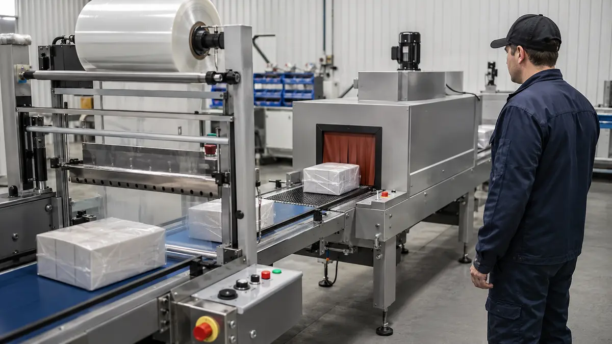
Important: Supplier-recommended settings are starting points. Heater calibration, airflow, line speed, sealing geometry, ambient conditions, film thickness, and product heat capacity can change the result.
The approval window should be wide enough for normal production variation while protecting the product. If the process requires extreme heat or produces frequent weak seals, burns, or wrinkles, investigate the film-line-product match rather than compensating indefinitely with one setting.
6. Puncture, Tear, Tensile, and Impact Performance
“Strength” is too vague for a useful specification. A film may resist a slow tensile load yet initiate a tear at a nick, or it may survive one impact method but fail against a sharp product corner. Select a method that represents the hazard, then report the film thickness, specimen direction, conditioning, speed, geometry, units, and failure definition.
| Property question | What the result can help describe | Essential comparison controls | What it does not prove |
|---|---|---|---|
| Tensile strength and elongation | Response to a controlled tensile load; ISO 527-3 specifies film and sheet test conditions within its scope | Method edition, specimen geometry, test speed, thickness, MD/TD, conditioning | Puncture resistance or finished-pack survival |
| Tear resistance | Propagation or initiation behavior under the selected tear method | Exact tear method, direction, thickness, notch or specimen preparation | Impact resistance or seal integrity |
| Puncture resistance | Response to a probe with a defined geometry and speed | Probe shape, speed, clamping, thickness, conditioning, force/energy units | Performance against every real product edge |
| Dart or other impact result | Failure under a specified impact configuration | Method, dart geometry, drop condition, thickness, conditioning, failure criterion | Equivalence to a different impact method or transport validation |
Gauge changes can affect results, but thickness alone is not a performance model. Resin grade, orientation, layer structure, seal areas, package geometry, and post-shrink stress also matter. Avoid comparing a result normalized by thickness with an unnormalized result unless the method and interpretation permit it.
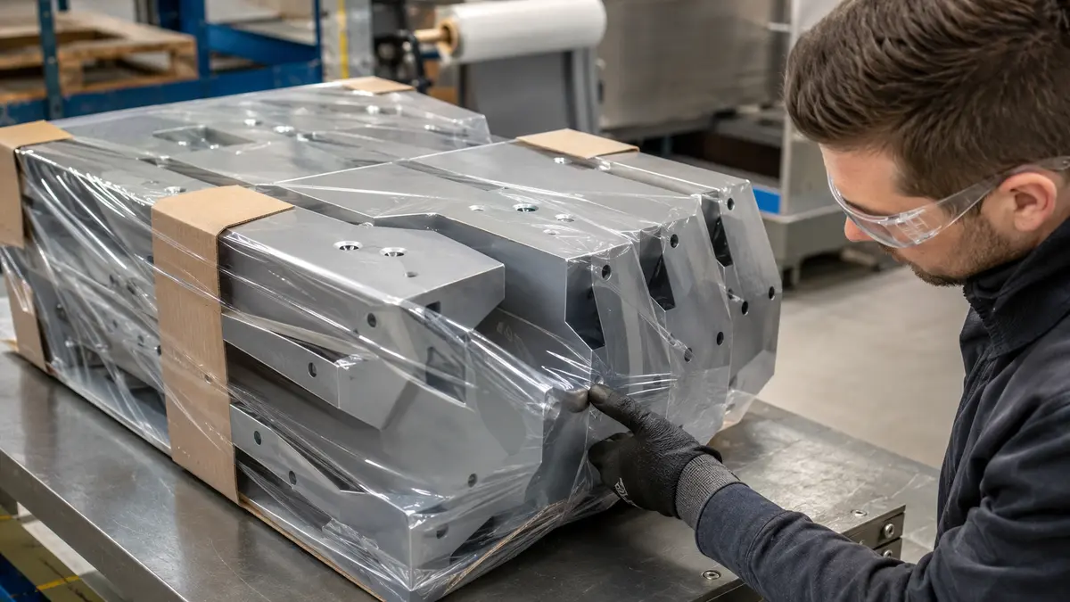
Finish with a package-level challenge that represents actual sharp edges, handling, vibration, abrasion, and distribution. Film tests help control incoming material; they do not automatically validate the complete packaged system.
7. Clarity, Haze, and Anti-Fog Performance
Optical requirements should begin with the viewing task. A retail pack that must show fine print through the film has a different requirement from an opaque transit bundle. “Clear” is therefore an incomplete specification. ASTM D1003 covers haze and luminous transmittance for essentially transparent plastics, but the method, procedure, specimen condition, and thickness still need to be reported.
| Use scenario | Main visual risk | Evidence to request | Acceptance boundary |
|---|---|---|---|
| Retail display under dry ambient conditions | Haze, distortion, wrinkles, gloss mismatch, or visible defects | Haze/transmittance data under the agreed method plus an approved packaged sample | Define viewing distance, lighting, background, and defect limit |
| Chilled product moving into a humid environment | Condensation obscures the product even when dry-film haze is low | Agreed anti-fog challenge with temperature, humidity, duration, film side, and scoring method | Set the minimum clear-view time and permitted droplet pattern |
| Printed or decorated shrink pack | Distortion or surface changes after shrinking | Artwork geometry, print-side description, shrink curve, ink/adhesion evidence, and line trial | Approve color, registration, distortion, and adhesion on the finished pack |
| Industrial bundle | Optical appearance may be secondary to inspection needs | Only the visibility and defect detection required by the operation | Do not pay for an undefined optical target |
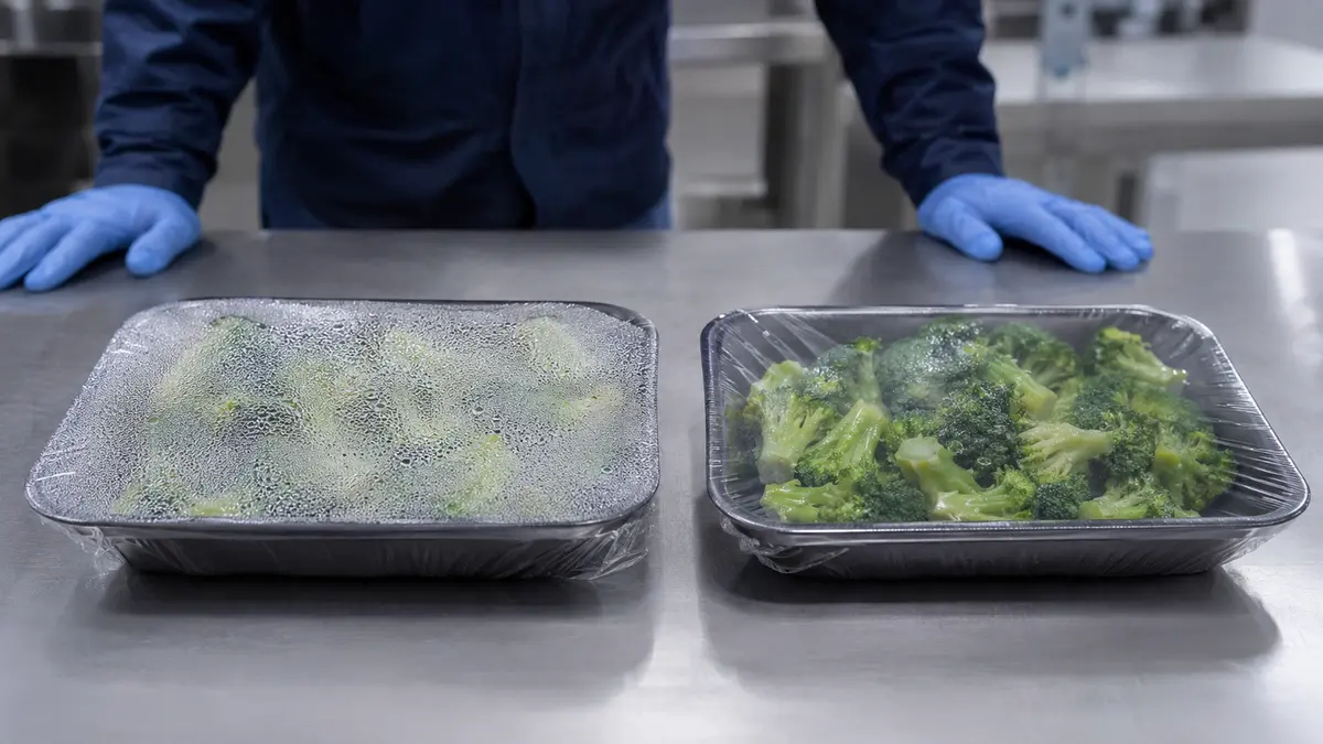
Anti-fog is a surface and use-condition question, not a synonym for low haze. Additive chemistry, surface orientation, storage, time, temperature cycling, and contamination can affect the result. State which film side faces the product and test the actual condensation sequence. An initial demonstration should not be described as permanent performance unless the agreed ageing and use conditions support that conclusion.
8. End-Use Protection and Compliance
The final element asks what the package must.
Close the specification with:
- The product’s sensitivity to moisture, oxygen, aroma loss or pickup, light, abrasion, contamination, and heat.
- OTR or WVTR targets only where relevant, with the method, temperature, relative humidity, thickness, test side, gas, units, and sample construction. ASTM D3985 and ASTM F1249 cover specific oxygen- and water-vapor-transmission methods; neither supplies a universal target.
- Any odor or aroma objective defined by an agreed analytical or sensory protocol, rather than an unsupported “odor barrier” label.
- The target country or market, food type if applicable, direct or indirect contact, contact duration, use temperature, and any processing or reheating condition.
- Product- and construction-specific declarations, authorizations, migration reports, or other documents applicable to that market and use. U.S. FDA authorization routes and EU Regulation No 10/2011 are use- and substance-specific frameworks, not generic product endorsements.
- Roll storage limits, shelf-life basis, sampling plan, change-control requirements, traceability, and the criteria for requalification.
- A final line and package trial using representative product, equipment, distribution conditions, and retained approval samples.
Warning: Do not accept “food grade,” “FDA approved,” “EU compliant,” “high barrier,” “recyclable,” or a shelf-life claim without checking the exact product, construction, market, use conditions, test method, report scope, and current supporting documents.
Taken together these eight elements turn a vague film request into a.
Related Bestypack Resources
- Comparison of Stretch Hood or Shrink Hood
- PE Shrink Film Polyethylene Shrink Film Manufacturer
- Shrink Wrap vs. Stretch Wrap: What’s the Difference?
- Differences Between Polyolefins, PVC And Polyethylene
- Anti Fog POF Shrink Film
 English
 Japanese
 French
 Spanish
 Korean
 Italian
 Portuguese
 Dutch
Dutch Arabic
 Russian
 German